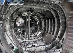
Siemens Syncrofit v15.1.1. Until recently there was no way to effectively manage the development of complex airframe assemblies and large aerostructures. Changed it all by enabling aerospace companies to efficiently capture, validate, and communicate both the engineering definition and the manufacturing assembly states of the aircraft – with particular emphasis on fastened structures. Airframe design is a very specialized work, which can be better supported if your tools allow you to work, for example, in terms of joints, fastener types, grip lengths and sealant specifications. Syncrofitsoftware from Siemens PLM Software addresses these challenges by providing a complete solution integrated into commercial 3D CAD systems specifically for the design and manufacture of airframe assemblies and large aerostructures. It creates digital, model-based definitions that minimize monotonous, lengthy design tasks while taking into account new manufacturing technologies and globally distributed design approaches.
plex assembly assemblies and large components of the aircraft body until the major Siemens company Syncrofit softwareIt was produced. Using this software, aerospace companies are allowed to efficiently capture, validate and communicate both engineering definitions and aircraft assembly status, with particular emphasis on interconnected structures. The program has tools that allow you to design joints, clamps, handlebars, seals, and more to simplify the design of the aircraft body. Syncrofit has solved all the challenges of designing aircraft and large structures by providing a comprehensive solution to 3D CAD systems. The Digital Definition program builds on a model that minimizes even and long-term design work while working globally, with new production technologies and distributed design approaches.
Here are some key Features of “Siemens Syncrofit v15.1.1” :
- Accurate and quick use of engineering requirements
- Automatic linkage between design and manufacturing systems
- No need to manually enter instructions for numerous attachments , joints and parts details
- Ability to define partial parts by connecting multiple shells Thickness and unique materials
- Automatic filling of thickness and material parameters according to the rules of the named name
- Creation of bonded material with the choice of application surface and a coordinate curve
- CPGU support for spot welding (CATIA V5 only)
- Possibility of permanent point geometry For vector spot welding
System Requirement
- Administrator privileges on the system where Syncrofit will be installed.
- Minimum of 128 Mbytes of RAM, or minimum requirement for the CAD system.
- Minimum of 200 Mbytes of disk space, on the drive where Syncrofit will be installed.
- One of the following NX or CATIA system / Operating system combinations (see below):
- Syncrofit 15.1.1 for CATIA V5
- CATIA V5 R25-R28 64-bit
- Syncrofit 15.1.1 for Siemens NX
- NX-10.0.2 + 64-bit ( to use NX-10 is the NX- 10.0.0 NX-10.0.0 )
- NX-11.0.1 + 64-bit
- NX-12.0.1 + 64-bit (to use NX-12 the minimum supported version is NX-12.0. 1)
- NX-1847 Series 64-bit (1847-1867)
- Operating System Support:
– Windows 7 SP1 ( 64-bit )
– Windows 10 ( 64-bit )
Download
Siemens Syncrofit v15.1.1


